Example upper floor deck design and drafting,
Labrador, Gold Coast

The following example design is of an upper floor covered deck with a carport under. There were also some internal home alterations as part of a larger renovation of a typical 1970's high set house.
The original house has most of its original layout, the rear balcony and stair had been enclosed and the roof was constructed from asbestos cement sheeting. The house is sited on a large block however it was set closer to the rear than the front, meaning any extension would ideally be placed to the front of the house, which had the benefit of giving the house a facelift whilst practically increasing the area under roof.
The upper floor deck has a side stair leading to the entry on the upper floor this effectively replaced the original stair and landing. To give the home owners more practical under cover outdoor living the deck roof is constructed from insulated panels, The shape extruded from the original low pitch roof. New gutters and fascias throughout tied in the new and existing roof lines and the asbestos roof was removed and replaced with Colorbond sheet roofing.
The deck structure against the existing ground levels was just heigh enough to be practical without significant digging out, although that would have been possible, digging out below the area of the carport would have created access issues to the garage below the existing house.
The finishes of this house was to be light coloured colorbond, render and stained timber. The existing house repainted to suit the additions.
Within the existing upper floor the bathroom and WC were combined to create a large family bathroom. The infilled rear balcony was extended into to enable the kitchen to be reconfigured and enlarged. The layout better suited to modern open plan entertaining.
The house extension and alteration plans, designed and drafted by SKETCH3D are modelled in a virtual 3D environment, and so include an interactive 3D walkthough at no cost to the client, used to explore and assist in the understanding of the design rather than trying to read 2D plans alone. A massive advantage for builders and home owners.
View further example house extension plans. For your own "Grand Design" or to discuss your home extension ideas Contact us
or call 0406 807833 for a chat and ideas about what could be designed into your home..
- Sketch render view - Site plan - Existing floor plans - Demolition plans - Existing house elevations -
- Proposed lower floor carport design - Proposed raised deck design -
- Proposed front and side home elevations - Proposed rear and side home elevations - Proposed cross Section A-A - Proposed Section B-B -
3D Visualisation - Sketch render effect

Projects involving external works benefit from 3D views as part of the drawing package to explain the intended design to all of the contractors as well as providing a cover sheet to the design documents. The 3D views clearly show the external facelift forming the coastal classic design of extended and renovated home. The use of black and white / greyscale keeps printing costs and file sizes low. The sketch render effect is easier on the eye than hard line CAD drawings, explains the design ideas and avoids the distraction of details that are otherwise covered in technical working drawings.. - Return to top
Raised deck and carport - Site Plan
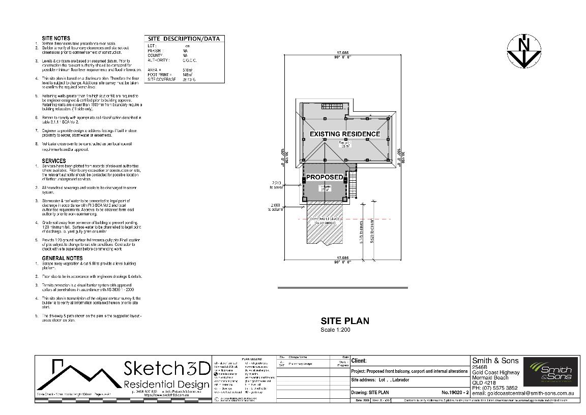
When drafting plans for a deck, carport, extension or renovation design, a site plan is required, showing the setbacks from the boundaries, the location of the works, site coverage and important site features that will affect the building application. - Return to top
Raised deck and carport - Existing Floor Plans
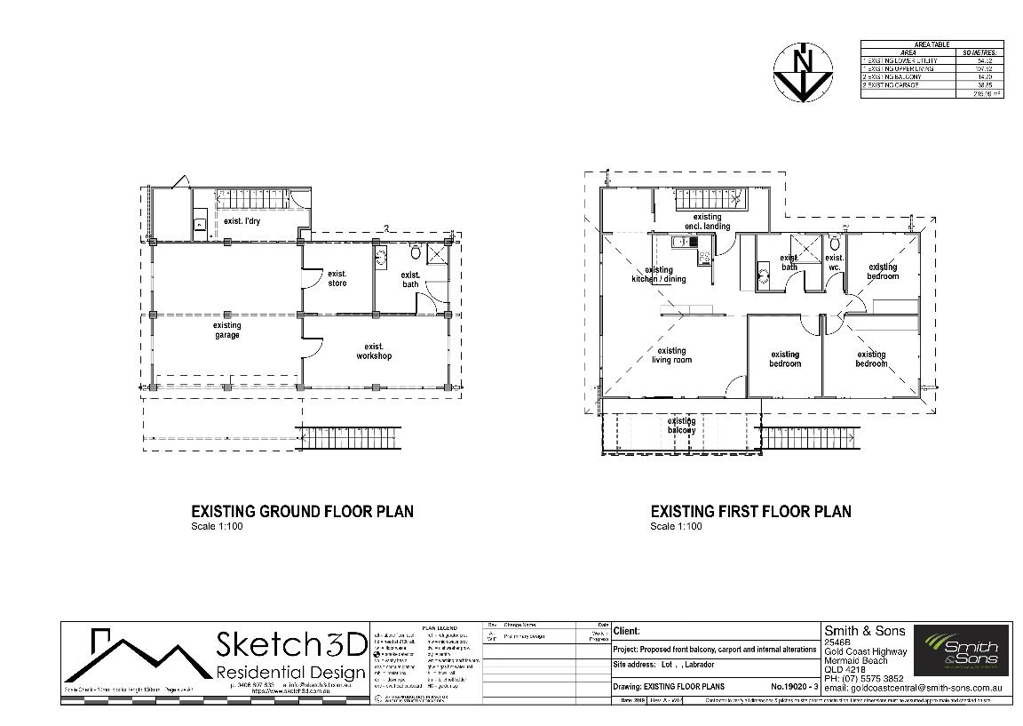
The existing upper and lower floor plans of this high set home have been drafted showing the relevant areas of the house as it stood before the new raised deck and alteration designs were applied. The existing first floor had a dated plan not suited to modern living and lacked single level entertainment space. The small front balcony was unsuitable for a family around tables and chairs. - Return to top
Existing house demolition plan
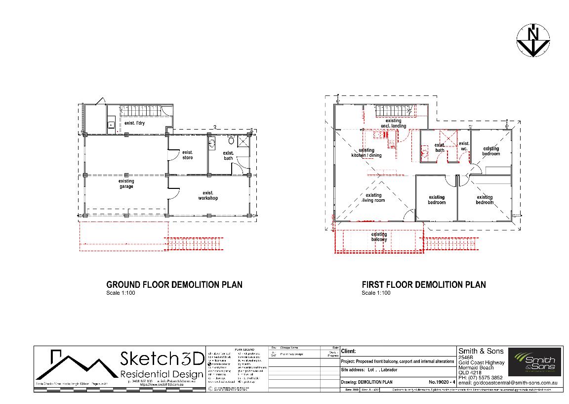
The demolition plan indicates which elements are being removed and modified, the purpose of this plan is to assist the builder planning the new works and identify which areas being modified might require additional making good. - Return to top
Existing house elevations
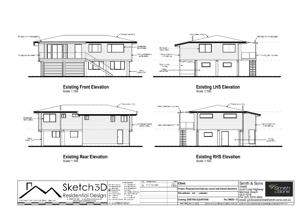
The existing house elevations are drafted showing the external appearance and finishes as the home stood before being modified and extended, this allows a comparison between the existing house and the proposed extension design and assists the builder in planning for the junction between new and old surfaces. - Return to top
Proposed carport plan below raised deck
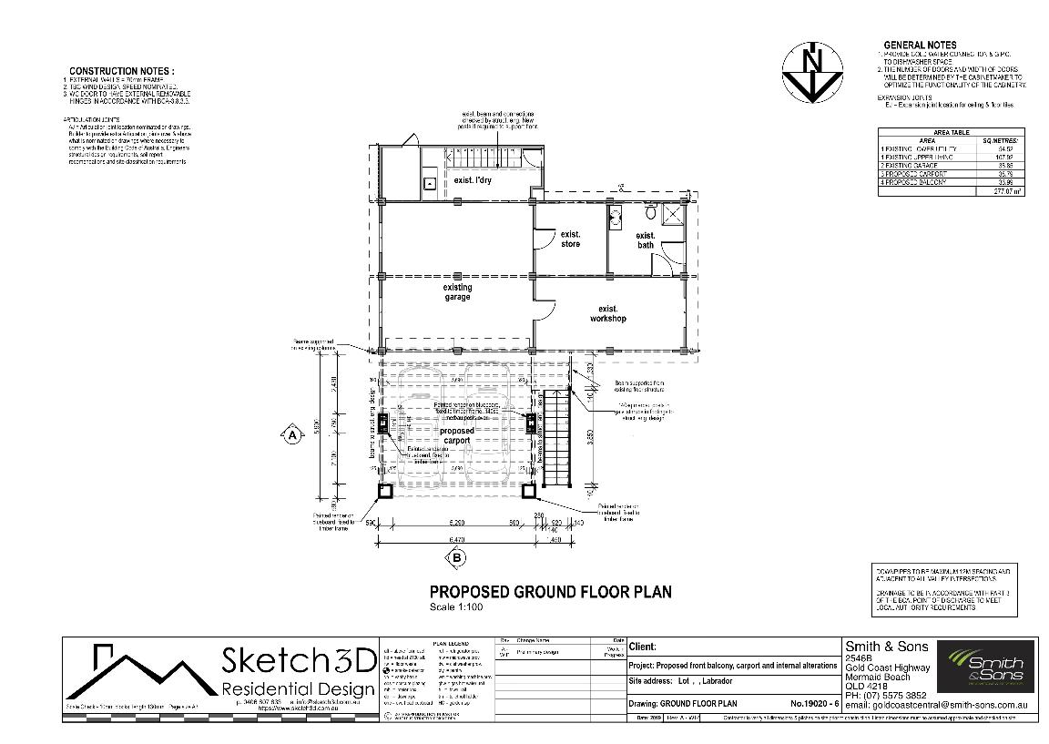
The carport plan, designed below a raised deck is set infront of the existing garage and within easy access to the new stairs leading to the upper floor main entrance. - Return to top
Proposed raised deck and home alterations plan
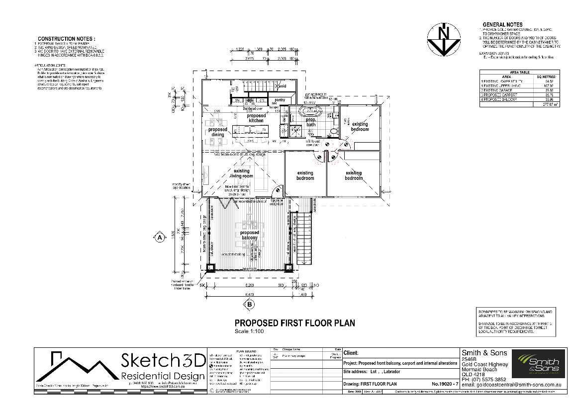
The proposed upper floor home extension design is made up of a raised deck over a carport below with new stairs leading from the lower level to the main entry at the upper level. The existing house has been altered to combine the existing bathroom with the WC creating a generous family bathroom. The kitchen has been extended into an existing enclosed rear balcony and reconfigured to create an open plan kitchen / dining / living room, more suited to modern living and entertaining. - Return to top
Proposed raised deck and carport front and side elevations
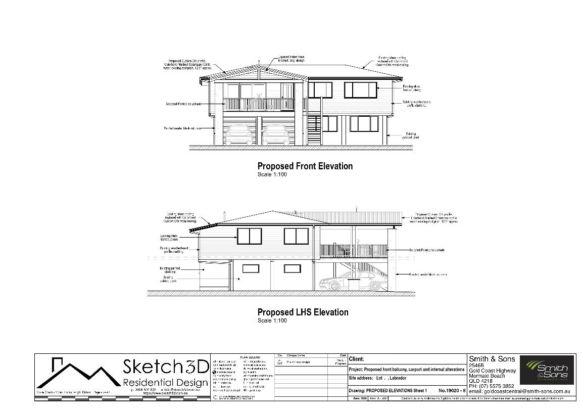
The proposed home extension design front and side elevations indicate the intended look of the house after raised deck and carport additions. - Return to top
Proposed raised deck and carport rear and side elevations
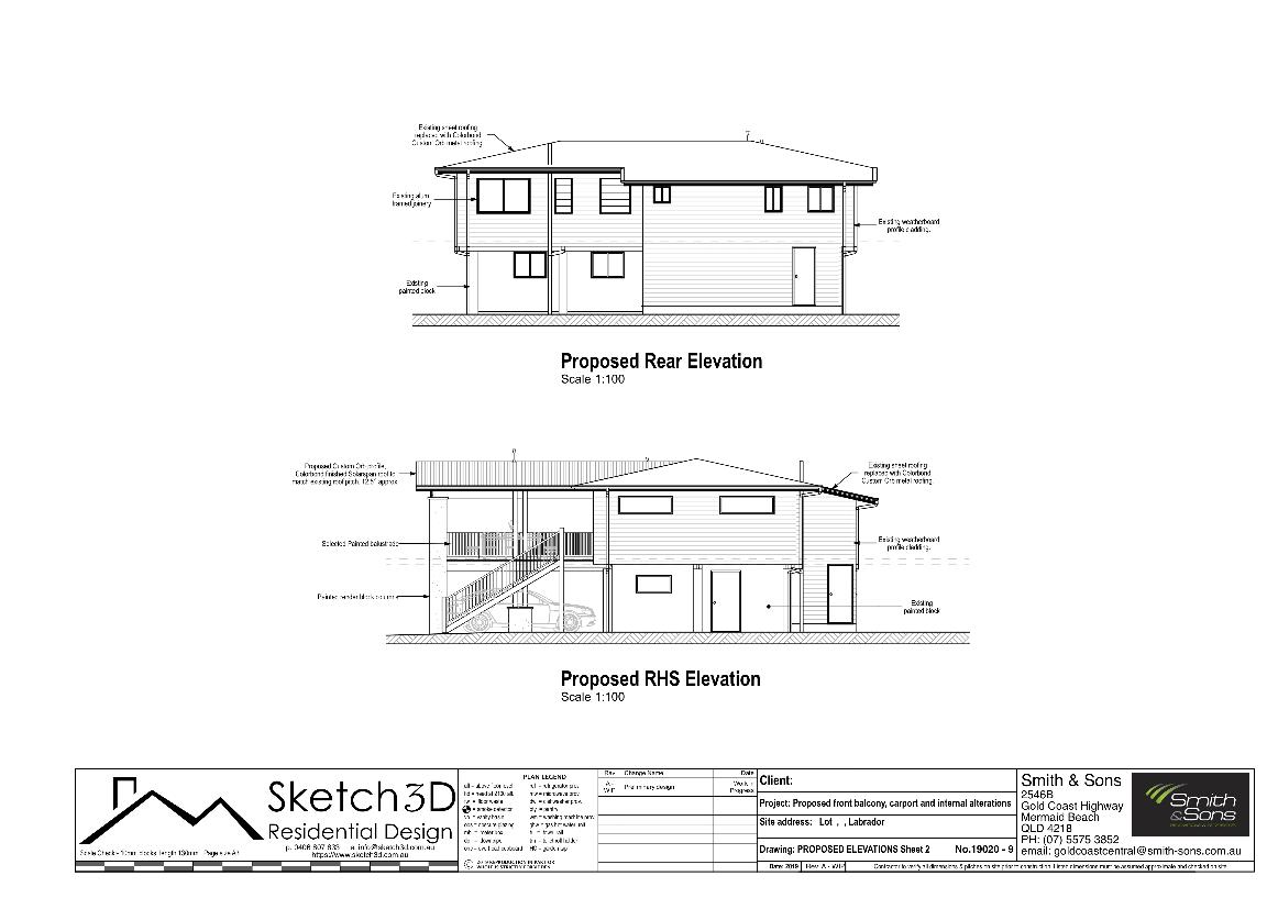
The proposed home extension design rear and side elevations indicate the intended look of the house after raised deck and carport additions. - Return to top
Proposed Raised deck and Carport Section A-A
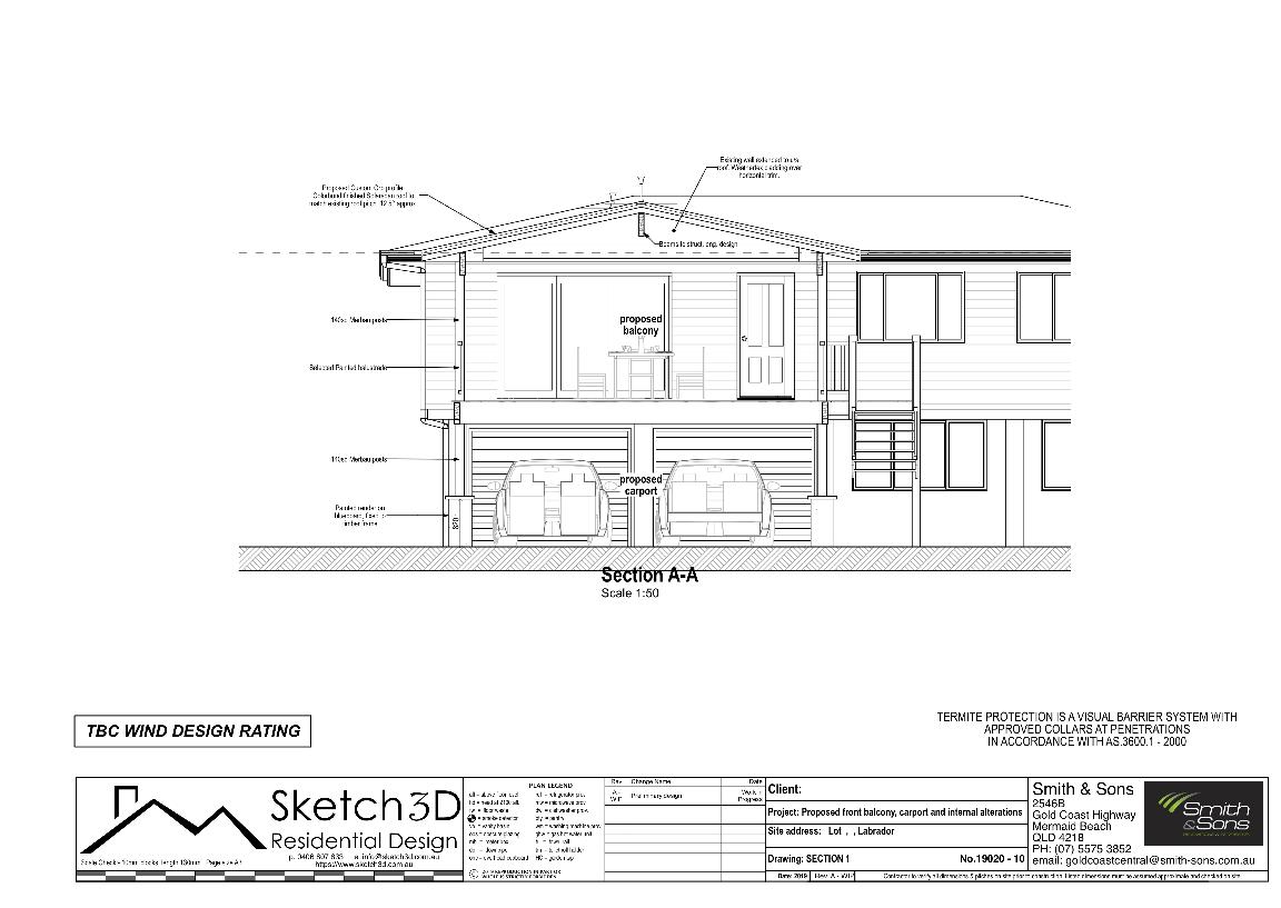
Sections through the proposed raised deck and carport design are included on the plans drafted, showing the relationship between levels, ceilings and notating structure in locations which explain the design intent and demonstrate compliance. - Return to top
Proposed Raised deck and Carport Section B-B

Sections through the proposed raised deck and carport design are included on the plans drafted, showing the relationship between levels, ceilings and notating structure in locations which explain the design intent and demonstrate compliance. This section cuts through the deck and carport then through the internal alterations of the existing high set home. - Return to top
Proposed raised deck roof plan
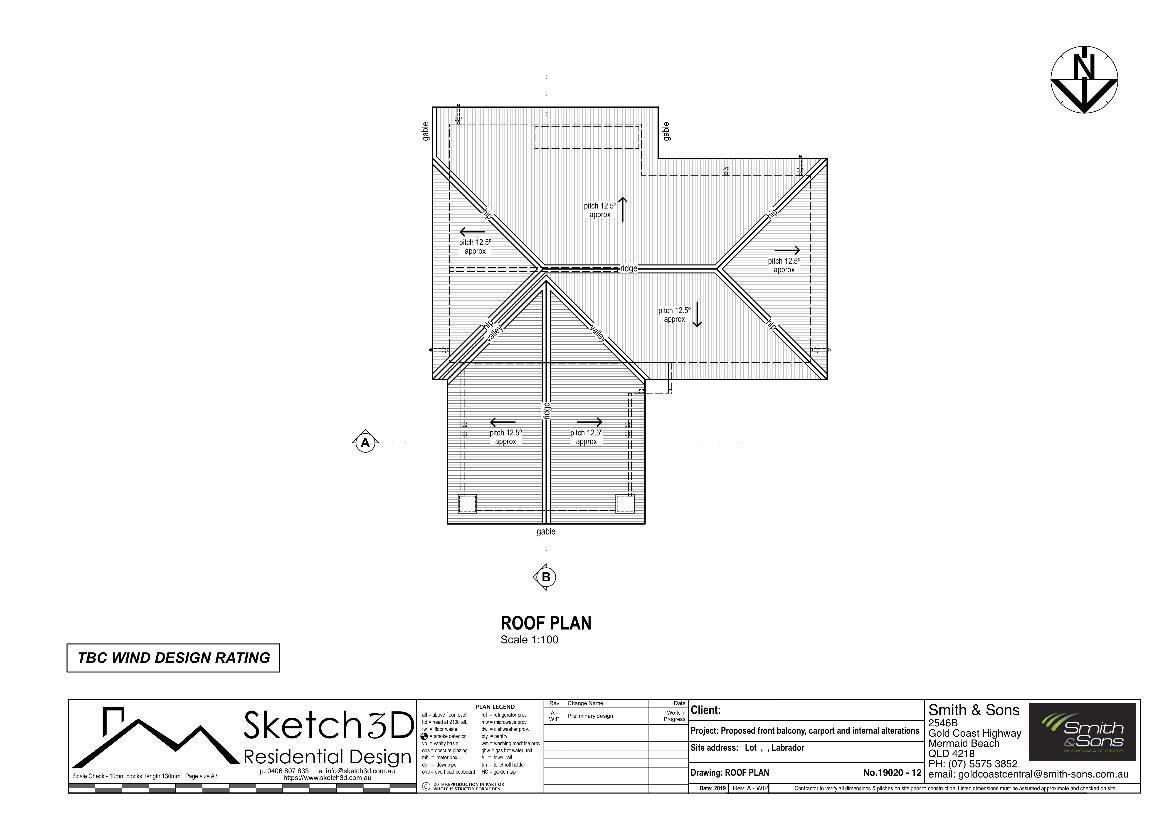
The roof plan shows the extent of the new roof and its relationship to the existing roof form. Indicating pitches, gables, valleys, ridges and hip. - Return to top
Proposed raised deck and carport electrical layout plan
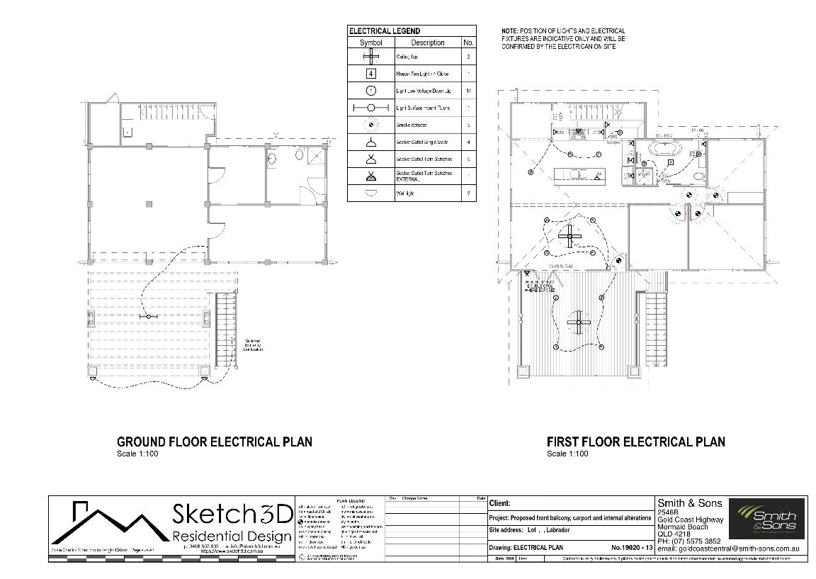
Electrical plans indicate the approximate location of the lighting, switches and power sockets as well as the smoke alarm positions required for compliance. - Return to top


